


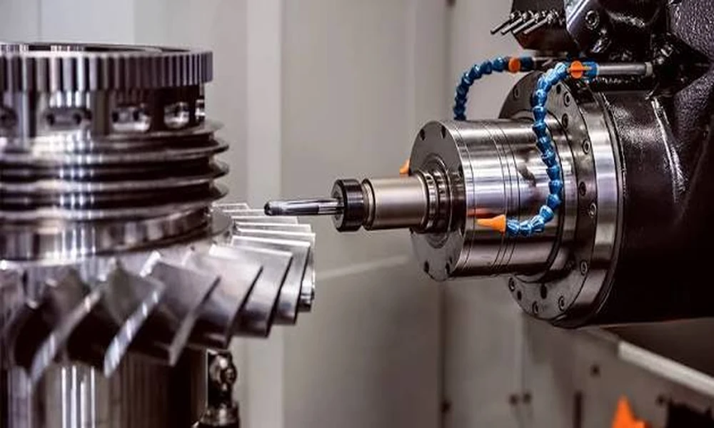



How to Check Metal Part Seating in a Compact Assembly Fixture
A clamp can reach the end of its stroke while an automotive bracket is still sitting on a burr or resting against the wrong locator. If the controller reads only the clamp cylinder, it sees a completed movement. A separate part check can add information about where the metal actually sits. Start by deciding whether the station needs to sense that a part is present, detect that a specific feature is in position, or measure a dimensional tolerance.
Choose the feature the switch can see
Place the sensing point where an incorrectly seated part changes the gap. A broad flange that stays close to the sensor even when a bracket is tilted may give the same result for good and bad loads. A locating tab near the seating surface may separate the two conditions more clearly. When the task requires a height or flatness value, include a measuring device with a suitable reference. A binary proximity signal has a different job.
The industrial proximity sensor catalogue distinguishes inductive metal detection from capacitive detection and compares mounting styles. For a metal fixture, pay particular attention to the clearance around the active face. A sensor that switches correctly on the bench can behave differently once it sits inside a steel pocket. Choose the position and mounting style together, then check the actual target alloy and size.
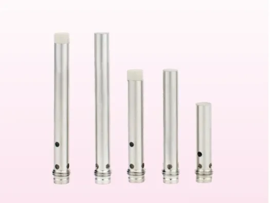
JD inductive proximity sensors in several housing lengths
Measure space for the connector as well as the probe
The JD connector type inductive sensors illustrate why two dimensions belong on the drawing. The series uses a 6.5 mm probe and offers M8 or M12 connector versions. Allow room behind the fixture for the mating cable and for a technician to disconnect it. Check the sensing distance, flush or nonflush mounting, output polarity and switching logic against the exact part number.
Run the states that matter at the line
In a controlled fixture trial, compare a correctly seated bracket, an empty pocket, a bracket held slightly proud and a position with representative metal chips near the sensing face. If good and bad parts produce the same result, change the target point or reconsider the measurement method. A larger nominal range may make the two states harder to separate.
Save the approved part number, target location and operating gap on the fixture drawing. Include the mating connector on the spare parts list. The production signal should say what was verified, such as bracket at locator, and leave clamp force, dimensional inspection and personnel protection to the functions designed for those tasks. On a fixture that accepts left and right brackets, show both sensing positions on the drawing. A single threshold can otherwise hide a difference in the target geometry.
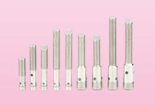
Second view of JD sensor housing and connector variants


Why Sealing and Cushioning Materials Deserve Attention in EV Battery Design – Auto Tirex
November 8, 2026[…] How to Check Metal Part Seating in a… […]